GTR Tech Corporation GT3-BH PC Chassis
Installation and Assembly

|
|
|
To build up a GT3, the first thing users need do is to remove the two cages, and drape all wiring outside the chassis, exposing the back plate of the unit. Installing the motherboard is straight-forward. It requires that the I/O shield be popped in along the back of the GT3, aligning of the mounting holes on the board with the standoffs, and then tightening the screws. There's little room to maneuver about inside the case, and we found that it was easier to tilt the board towards the front first, slipping it under the HDD/slimCD mounting bracket, and then downwards. It's also suggested that much of the cabling be connected now, as it will be much harder to complete later on.
That's probably the easiest part of the process, and from there it gets a bit tricky. If you're the type of builder who likes a challenge, or likes figuring out puzzles, then you'll enjoy the next step. For others, it could be quite frustrating. This next step involves setting up the Feature Module, and as the manual says, it's best to take a moment and familiarize yourself with it because it's quite different from anything else we've dealt with before.
Based on the alignment of the slots on the motherboard and the cards being installed, the Feature Module can be reconfigured by adding or removing spacers and the included risers, but it's not always quite clear what the end result should look like. The manuals we used were a bit raw, lacking any real detail, although GTR Tech has been working on revised versions that will hopefully explain things much clearer. They also plan on providing instructional videos on their website for further assistance.
With some persistence, we were able to get the riser cards installed, and expansion cards into the risers. We were, however, a bit wary of pushing down too hard on the PCI riser's ribbon cable for fear of breaking it. We decided to rock the cable into an open PCI slot, which seemed to work just fine. The PCI-E riser card installs directly into the first PCI-E slot, just as if it were a graphics card. For the sake of clarity, we've removed all of the components from the Feature Module to show how this inserts into a motherboard in the above pictures.
After installation, please note that the video card gets mounted cooler-side down, facing towards the mainboard. This configuration could result in warmer air being trapped between the two layers of PCB, but the lower mounted case-fan should come into play here, by forcing cooler air into this zone. Cards with larger heatsinks will still come quite close to the board itself, however.
The next step requires reintroducing the HDD/SlimCD module and re-attaching the rest of the power cables and other wires. This is where a good deal of time may also be spent, especially when it comes to preventing the various cables from blocking the fans. Again, patience will be well rewarded here. Don't go in expecting that the GT3 is just another run-of-the-mill installation or you will probably wind up frustrated. Set aside some time. Read the manual. Watch the video. It's definitely different from anything you've experienced before.
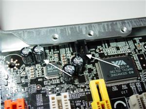
We also wanted to point out an issue that popped up during installation that may affect some buyers. It's quite possible due to the various possible layouts of components that some motherboards may not work with the GT3. In fact, our very first build consisted of using an MSI P965 Platinum motherboard, but we were quickly thwarted when the placement of the audio header and a handful of capacitors ran up against the inside lip of the chassis. Due to this issue, GTR Tech is working on a list of motherboards and other components that work well with the GT3...


